U-Series
This catalogue of coilformers contains information on all our products of the U-Series
Transducers with U-ferrites are used in power or pulse applications, high voltage transducers and TV's.
We supply coilformers made in high quality thermoplastics, matching your production requirements.
Wherever high-temperature soldering processes are used, we recommend irradiation cross-linked thermoplastics. Cross-linked materials can be exposed to short, but very high peak temperatures. Beside improved production aspects there may be also interesting cost advantages.
Our extensive range of modular tooling allows constructional changes to customers specification by simple changing tool inserts. In addition the modular tooling system allows short tooling times and can be very cost effective.
Should you need further assistance we look forward to hearing from you.
U Standard Coilformers
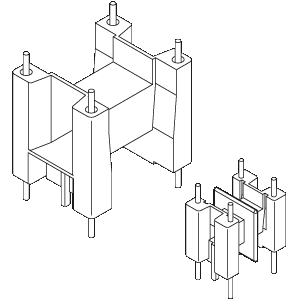
The coilformers are made in gfr Polyamide PA66 of type p6g (RTI long-range temperature +125°C). Pin material: tin bronze, tinned. Maximum solder temperature 350°C, 2 sec.
Special materials - e.g. irradiated cross-linked - and designs on request, dimensions in mm/inch.
The coilformers have through-hole round pins for contacts on both sides. The terminal strips usually feature "noses" which provide tension-relief, identification-noses (hole in the pcb) and "stand-offs" which allow clean soldering of the wires and of the coilformer onto the pcb.

U 25 Universal Coilformers with m-pins
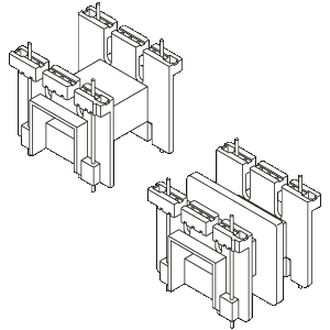
The coilformers are made in gfr Polyamide PA66 of type A RV250 nat. (RTI long-range temperature +100°C). Pin material: tin bronze, tinned. Maximum solder temperature 350°C, 2 sec.
Special materials - e.g. irradiated cross-linked - and designs on request, dimensions in mm/inch.
The coilformers have through-hole round pins for contacts on both sides. They can be secured to the pcb with self-tapping screws. Wide stand-offs provide a solid area of support and allow clean soldering of the wires and of the coilformer onto the pcb.

U 25 Universal Coilformers with h-pins or z-pins
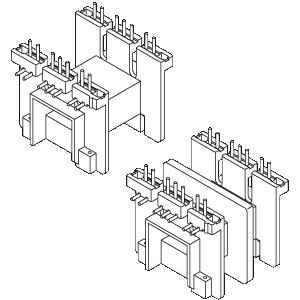
The coilformers are made in gfr Polyamide PA66 of type A RV250 nat. (RTI long-range temperature +100°C). Pin material: tin bronze, tinned. Maximum solder temperature 350°C, 2 sec.
Special materials - e.g. irradiated cross-linked - and designs on request, dimensions in mm/inch.
Version with h-pins for radial binding-on of thin wires and litzwires. Version with z-pins which takes up less space on the pcb. The coilformers can be secured to the pcb with self-tapping screws. Wide stand-offs provide a solid area of support and allow clean soldering of the wires and of the coilformer onto the pcb.

Spring-Clip SB-U
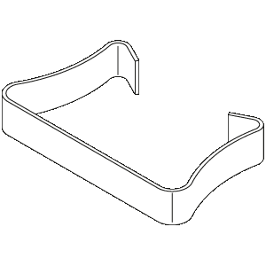
Glueing methods are usually used to connect and secure the ferrite cores. Glues, such as Araldite, require the ferrite cores to be kept under constant pressure until the glue has hardened. A more advantageous and quicker method is by using stainless steel clips SB. The holding pressure is almost constant over the whole operating temperature range.
One clip is required to assemble a wound coilformer with one pair of ferrite cores. The use of a drop of glue is recommended, to connect the ferrites to the coilformer and to prevent frequency noise.
Dimensions in mm/inch.
When ordering please quote type and order-code.

Ordering Example
Please kindly take all details which are necessary to execute your order correctly from the ordering example (pdf-file).

Additional Product Informations
For explanatory and more detailed information on this coilformer-series please kindly see the attached pdf-file.
- Information of U-Series
- Survey of Solder-pins for U class coilformers
- List of Thermoplastic Materials
- U Ferrite Cores
